Showing posts with label 5G-NR. Show all posts

RNTI

 What is RNTI?

In 5G networks, each UE (User Equipment) needs to be uniquely identified for both signaling and data transmissions. The RNTI (Radio Network Temporary Identifier) is used for this purpose. It’s a temporary, dynamic identifier that helps the network distinguish between UEs and manage resource allocation, scheduling, and communication over the radio interface.

Key Points:

  • Temporary: RNTI is assigned temporarily during an active session and can be released or reassigned as needed.
  • Efficient Communication: RNTI helps the gNB manage different users, messages, and services efficiently.
  • Scalability: Supports a wide range of users and services in dense 5G environments, ensuring network scalability.

2. Types of RNTIs in 5G

There are several different types of RNTIs in 5G, each serving a specific purpose in the network for various control and data functions.

2.1. SI-RNTI (System Information RNTI)

  • Purpose: Used to transmit system information to all UEs.
  • Usage: This RNTI is used when the gNB broadcasts system information blocks (SIBs) to all UEs in the network. All UEs use the same SI-RNTI to access system information.
  • Scope: Broadcast over the network, not unique to a specific UE.

2.2. P-RNTI (Paging RNTI)

  • Purpose: Used for paging UEs that are in idle or inactive mode.
  • Usage: When the network needs to contact a UE that is in idle mode, it uses the P-RNTI to broadcast a paging message. This message will inform the UE to reestablish a connection with the network.
  • Scope: Broadcasted across the cell, not unique to one UE.

2.3. C-RNTI (Cell RNTI)

  • Purpose: A unique identifier used for UE-specific communications.
  • Usage: C-RNTI is assigned to a UE when it is connected to a specific cell. It is used during dedicated communication between the UE and the network, such as during a connection for voice calls, data transmission, and control signaling.
  • Scope: Unique to each UE in a specific cell. It ensures the UE can communicate without interference from others.

2.4. RA-RNTI (Random Access RNTI)

  • Purpose: Facilitates the random access procedure.
  • Usage: The UE uses the RA-RNTI during the Random Access (RA) procedure to initiate a connection with the gNB, such as when entering the network or switching between cells. RA-RNTI is generated based on the Random Access Occasion (RAO).
  • Scope: Temporarily assigned during the RA process to a group of UEs using the same access occasion.

2.5. TC-RNTI (Temporary C-RNTI)

  • Purpose: Assigned during the Random Access process to temporarily identify a UE.
  • Usage: When the UE attempts a random access procedure (e.g., during a handover), it is assigned a TC-RNTI before the final C-RNTI is given. This helps maintain the communication session until a permanent identifier (C-RNTI) is allocated.
  • Scope: Temporary identifier until the UE gets the final C-RNTI.

2.6. SP-CSI-RNTI (Semi-Persistent CSI-RNTI)

  • Purpose: Used for scheduling CSI (Channel State Information) reporting.
  • Usage: The SP-CSI-RNTI is used for UEs with semi-persistent CSI reporting, helping the network optimize resource allocation based on channel quality feedback.
  • Scope: Assigned to UEs involved in semi-persistent scheduling scenarios.

2.7. TP-RNTI (Temporary Paging RNTI)

  • Purpose: Used during the paging process when a paging message is sent to a specific group of UEs.
  • Usage: TP-RNTI is used when multiple UEs share a paging occasion, helping to identify the UEs that should respond to the paging message.
  • Scope: Shared by a group of UEs that are paged together.

2.8. CS-RNTI (Cell-Specific RNTI)

  • Purpose: Used for UEs engaged in cell-specific communication for broadcast or multicast transmissions.
  • Usage: Helps UEs that participate in multicast or broadcast services like multimedia streaming.
  • Scope: Assigned to UEs based on cell-specific operations.

2.9. MBMS-RNTI (Multimedia Broadcast Multicast Service-RNTI)

  • Purpose: Used for broadcast and multicast services (MBMS) in 5G networks.
  • Usage: MBMS-RNTI is assigned to UEs that participate in multimedia broadcast services, such as video streaming to multiple users simultaneously.
  • Scope: Assigned for a specific MBMS session.

3. Role of RNTI in Network Operations

RNTI plays a crucial role in ensuring that the 5G network can handle a large number of UEs efficiently. Here’s how RNTI contributes to 5G operations:

  • Efficient Resource Management: By assigning unique identifiers (RNTIs) to different UEs and communication processes, the gNB can efficiently schedule resources and manage uplink and downlink traffic.
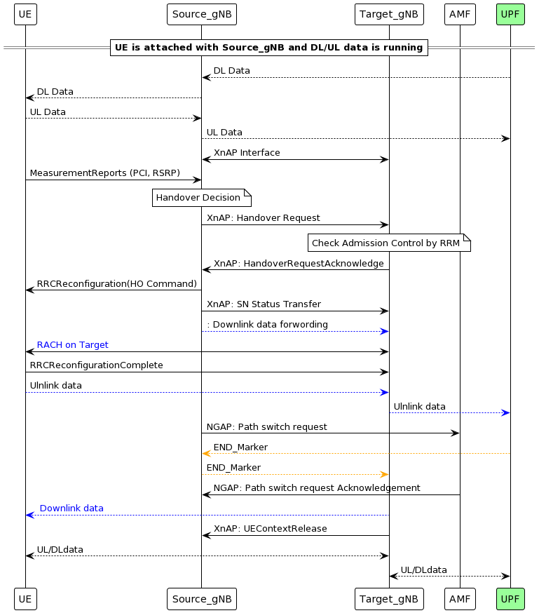
  • Mobility Management: As UEs move between cells, RNTIs ensure that seamless handovers occur without drops in connectivity. For example, C-RNTI and TC-RNTI work together during handovers.
  • Paging and Broadcast: Paging messages using P-RNTI and broadcasting system information using SI-RNTI are vital for UEs that are in idle mode or just entering the network.
  • Collision Avoidance: In the Random Access procedure, RA-RNTI helps prevent collisions between UEs trying to access the network simultaneously.

SIB1 in 5G:

SIB1 (System Information Block Type 1) from 3GPP

SIB1 (System Information Block Type 1), as defined by the 3GPP TS 38.331, contains essential parameters for the initial access, cell selection, and network configuration in 5G NR (New Radio). These parameters are presented in the form of Information Elements (IEs), which provide the necessary information to the user equipment (UE) to connect and operate within a 5G network.

Below is a detailed breakdown of the key Information Elements (IEs) present in SIB1, along with their functions, as specified by 3GPP standards.


1. PLMN-IdentityList

  • Description: This IE provides a list of one or more Public Land Mobile Networks (PLMNs) that the cell broadcasts.
  • Purpose: Helps the UE identify which PLMNs it can connect to, enabling network access when the UE’s PLMN matches an allowed PLMN.
  • Key Parameters:
    • PLMN-Identity: Contains the MCC (Mobile Country Code) and MNC (Mobile Network Code) identifying the network operator.
    • TrackingAreaCode (TAC): Identifies the tracking area where the gNB (gNodeB or base station) is located.

2. CellAccessRelatedInfo

  • Description: Provides information about cell access restrictions and reselection policies.
  • Purpose: Guides the UE on whether it can access the cell and under what conditions it can reselect to other cells.
  • Key Parameters:
    • CellBarred: Indicates if the cell is barred (i.e., the UE should not attempt to connect to this cell). If set to "barred," the UE must avoid this cell.
    • IntraFreqReselection: Determines whether the UE is allowed to reselect other cells on the same frequency.

3. ServingCellConfigCommon

  • Description: This IE contains the common configuration information related to the serving cell.
  • Purpose: Provides the UE with essential configuration parameters for operation in the serving cell, including subcarrier spacing and beam management.
  • Key Parameters:
    • SubcarrierSpacingCommon: Defines the subcarrier spacing to be used for downlink and uplink communication. The values can be 15 kHz, 30 kHz, 60 kHz, 120 kHz, or 240 kHz.
    • SSB-PositionsInBurst: Specifies the position of Synchronization Signal Blocks (SSB) in the burst. This helps the UE find and align with the SSB transmission for synchronization and initial access.

4. Frequency Band Indicator

  • Description: Indicates the frequency band that the gNB is operating on.
  • Purpose: Enables the UE to know which frequency band it should use for communication and whether it matches its capabilities.
  • Key Parameters:
    • NR-ARFCN: The absolute radio frequency channel number that defines the specific carrier frequency in use.

5. System Frame Number (SFN)

  • Description: The system frame number that indicates the current frame within the radio frame structure.
  • Purpose: Ensures that the UE is synchronized with the gNB in terms of timing, which is necessary for effective communication.
  • Key Parameters:
    • SFN: A number between 0 and 1023, identifying the frame in which the UE and network are currently operating.

6. SIB1 Periodicity

  • Description: Indicates how often SIB1 is broadcast by the gNB.
  • Purpose: Allows the UE to schedule when to receive SIB1 and ensures that the UE can retrieve the necessary system information if it misses the current broadcast.
  • Typical values: SIB1 is usually broadcast every 160 ms, 320 ms, or other standard intervals as defined by network configuration.

7. RACH-ConfigCommon

  • Description: Contains configuration parameters for the Random Access Channel (RACH) procedure, which is used by the UE to initiate connection with the network.
  • Purpose: Provides the UE with the configuration needed to perform random access when it first connects to the network or when recovering from radio link failure.
  • Key Parameters:
    • prach-ConfigIndex: Specifies the configuration index for PRACH (Physical Random Access Channel) parameters.
    • Msg1-FDM: Specifies how many frequency division multiplexing (FDM) opportunities are available for Msg1 in random access.
    • RACH-Configuration: Defines the number of preambles and the time/frequency resources used for the random access procedure.

8. PDCCH-ConfigSIB1

  • Description: Configures the Physical Downlink Control Channel (PDCCH) for SIB1.
  • Purpose: Specifies the parameters for the PDCCH that carries the scheduling information for SIB1, enabling the UE to decode the control information properly.
  • Key Parameters:
    • ControlResourceSetZero: Defines the set of resources in the control channel for SIB1 transmission.
    • SearchSpaceZero: Specifies the search space that the UE must monitor for the PDCCH carrying SIB1.

9. Paging Information

  • Description: Provides information on how the network pages the UE when it is in idle mode.
  • Purpose: Helps the UE know when and how to monitor for paging messages, ensuring it can receive calls, messages, or notifications while conserving battery power.
  • Key Parameters:
    • PagingCycle: Determines how frequently the UE checks for paging messages. A longer cycle reduces power consumption, while a shorter cycle improves responsiveness.
    • PagingOffset: Specifies the offset within the paging cycle at which the UE should listen for paging messages.

10. Q-RxLevMin

  • Description: Specifies the minimum required reference signal received power (RSRP) level for the UE to access the cell.
  • Purpose: Ensures that the UE only tries to access the cell if the signal strength meets a certain threshold, improving the chances of a successful connection.
  • Key Parameters:
    • Q-RxLevMin: A value representing the minimum signal strength (in dBm) that the UE needs to consider the cell as suitable for connection.

11. P-Max

  • Description: Defines the maximum allowed transmit power for the UE in the current cell.
  • Purpose: Controls the UE’s transmit power, ensuring that it stays within the network's power limits and avoids causing interference with other devices.
  • Key Parameters:
    • P-Max: Specifies the maximum transmit power level, typically measured in dBm, for uplink transmission.

12. TimeAlignmentTimerCommon

  • Description: Defines the duration of the timing alignment timer used to synchronize uplink transmissions between the UE and the gNB.
  • Purpose: Ensures that the UE maintains proper time alignment with the gNB during uplink transmissions. If the timer expires, the UE must initiate a new random access procedure to regain synchronization.
  • Key Parameters:
    • TimeAlignmentTimer: Specifies the timer duration, after which the UE assumes its timing alignment with the network is lost.

13. Beam Management Information

  • Description: Provides configuration information related to beamforming, a key technology in 5G that enhances signal quality by focusing the transmission in a specific direction.
  • Purpose: Helps the UE optimize communication with the gNB, especially in environments where beamforming is used for high-frequency bands.
  • Key Parameters:
    • BeamManagementConfig: Specifies parameters for managing multiple beams used by the UE and gNB for signal transmission and reception.

Conclusion

The Information Elements (IEs) in SIB1 provide vital data that helps the UE perform initial network access, cell selection, random access, and synchronization in a 5G network. These IEs are carefully structured according to 3GPP standards to ensure that the UE has all the necessary parameters to establish and maintain communication with the 5G New Radio (NR) network efficiently.

5G(NR): Xn Based Handover

5G(NR): Xn Based Handover


Introduction:

The basic handover procedures is same in any networks, i.e. UE reports measurement report with neighbor cell PCI and signal strength to source cell, source cell take the decision to start handover procedure to best target cell and Target Cell completes the Handover procedure.


Impotent Pointers for Xn Handover:

  1. Signal strength of both source gNB and target gNB should be reachable to UE during the HO. 
  2. Xn Handover is similar X2 Handover in 4G LTE
  3. XnAP interface must be established between source and Target gNB.
  4. This type of Handover is only applicable for intra-AMF mobility, i.e. Xn handover cannot be used if Source and Target gNB is connected to different AMF
  5. Xn Handover can be Intra Frequency HO and Inter Frequency HO
  6. Source and Target gNB can be connected with two different UPFs
  7. Tracking Area code should be same. Re-Registration is required after Successful Handover if the Source gNB and Target gNB belong to different Tracking Area (TAC)
  8. Xn Handover is Faster as Compare to N2/NGAP Handover due to short signalling path and 5G Core involved in only for switch the PDU session path


High level setup diagram:

      where both the gNB is served by same AMF and UPF. and for XnHO, XnAP interface is active between source gNB and target gNB.


Signaling Exchange b/w Source gNB and target gNB.


5G(NR): NG Based Handover

 5G(NR): NG Based Handover

Introduction:

The basic handover procedures is same in any networks, i.e. UE reports measurement report with neighbor cell PCI and signal strength to source cell, source cell take the decision to start handover procedure to best target cell and Target Cell completes the Handover procedure.

  •  In 5G NG Handover is very similar to S1 Handover in LTE. NG handover is also called inter gNB and Intra AMF Handover. NG handover take place when X2 interface is not available between source gNB and Target gNB or if X2 interface is there but XnHO is not permitted restriction is there at gNB configuration. 
  • NG(N2) Handover can be Intra Frequency HO and Inter Frequency HO both.
  • Below is the NG handover architecture in 5G.


Below is the flow diagram of NG(N2) handover.


5G-SA Call Flow: Messages mapped with channels:

 5G-SA Call Flow:

In this section of blog, we have tried to map some of the massages of 5G-SA call flow with channels (physical/Transport/Logical), SRBs over which messages are being transfer, mapped coreset and search space with the messages and RLC mode used during UE attached.


What is ARQ and HARQ?

What is ARQ and HARQ?

ARQ stands for Automatic Repeat Request. This is the protocol used at data link layer. it is an error-control strategy that is used in a two-way communication system.  It is used to achieve reliable data transmission over an unreliable source or service.

 It uses CRC(cyclic redundancy check) to determine, whether the packet received is correct or not. If the packet is received correctly at receiver side, receiver send ACK to the transmitter, but in case if the packet is not received correctly at receiver side, receiver send NACK to the transmitter. And then after receiving NACK from receiver, transmitter re-transmits the same packet again.


HARQ does not retransmit packet/PDU as it is; as done by ARQ technique. HARQ modifies certain physical parameters before retransmission.


The HARQ is a technique when the receiver gets a new data with some errors then it tries to make correction if the error is minor, but if the error is not minor then it sends re-transmission request to the sender. After getting the data again, it combines the new received data with previous erroneous data.


If some packets passed from HARQ to upper layer with a little bit errors which might be acceptable for some applications, but in any case there is one more mechanism which is ARQ or Automatic Repeat Request. The ARQ mechanism takes care of residual errors which passed from HARQ. If there is an error then it discards the packets and a new re-transmission is requested from the sender. ARQ is an error control protocol.


HARQ:
1. It works at Physical layer but controlled by MAC layer.
2. If the received data has an error then the receiver buffers the data and requests a re-transmission from the transmitter

3. HARQ  works for both UM and AM mode.

4. HARQ provides very fast retransmission which is suitable for high speeds (eg voice call).

ARQ: 
1. It works at RLC layer for RLC AM MODE ONLY.
2. If the received data has an error which is passed through HARQ then it is discarded, and a new re-transmission is requested from the transmitter.

3. ARQ is responsible for reliability.

5G-NR: NRF


Role of NRF in 5G architecture:

Network Repository Function (NRF)

The NRF maintains a record of all the 5G elements that are available in the network and their supported services. It allows other NF instances to subscribe and be notified of registrations from NF instances of a given type


The NRF supports discovery mechanisms that allows 5G elements to discover each other and get updated status of the desired elements.

The NRF supports the following functions:

  • Maintains the profiles of the available NF instances and their supported services in the 5G core network
  • Allows consumer NF instances to discover other providers NF instances in the 5G core network
  • Allows NF instances to track the status of other NF instances

 It supports the above functions through the following services:

  • Management Services (Nnrf_NFManagement)
  • Discovery Services (Nnrf_NFDiscovery)

Management Services (nrf_NFManagement.

This will handles the following service operations:
  • Receives and handles NFRegister service requests from the Nfs.
  • Receives and handles NFDeregister service requests from the NFs
  • Stores the registered profiles in its own data store using the database service.
  • Receives and handles NFDeregister service requests from the Nfs.
  • Receives and handles the Heart-beat messages from the NFs
  • Monitors the heart-beat expiry, mark the NF profiles as suspended and take appropriate action on the suspended NF profiles.
  • NF profile Retrieval.
  • Receives and handles NFStatusSubscribe service requests from the NFs.
  • Receives and handles NFStatusUnsubscribe service requests from the NFs.
  • Receives and handles NFNotify service requests from the NFs
  • Stores the subscription data in its own data store using the database service
Discovery Services (Nnrf_NFDiscoveryService)

This will handles the following service operations:
  • Receives and handles NFDiscover service requests from the Nfs.

 
NRF Functions/Procedure Support:

The NRF interacts with every other element in the 5G core network and it supports the above functions through the following services over HTTPS protocols:
  • Management Services
  • Discovery Services


Supports the following Functions/Procedure-
1) NRF Management Services-
The NRF Management service is identified by the service operation name Nnrf_NFManagement. NRF supports the following management services.
 
Register NF instance (NFRegister):- It allows an NF Instance to register its NF profile in the NRF; it includes the registration of the general parameters of the NF Instance, together with the list of services exposed by the NF Instance. This service operation is not allowed to be invoked from an NRF in a different PLMN. 
 
Update NF instance (NFUpdate): Enables an NF instance to partially update or replace the parameters of its NF profile in the NRF. It also allows to add or delete services provided by the NF instance.
 
De-register NF instance (NFDeregister): It allows an NF Instance to de-register its NF profile in the NRF, including the services offered by the NF Instance. This service operation is not allowed to be invoked from an NRF in a different PLMN.
 
Subscribe to Status (NFStatusSubscribe): Enables an NF instance to subscribe the status changes of other NF instances registered in the NRF.
 
Unsubscribe to Status (NFStatusUnsubscribe): Enables an NF instance to unsubscribe the status changes of other NF instances.
 
Receive Notifications of Status (NFStatusNotify): Enables the NRF to notify changes status of NF instances to any subscriber of NF status. Changes also include information regarding newly registered and de-registered NFs.


2) Discovery Service:

The NRF Discovery service is identified by the service operation name Nnrf_NFDiscoveryService.
Nnrf_NFDiscoveryService- It also allows an NF to subscribe to be notified of registration, de-registration and profile changes of NF Instance along with their NF Services.


5G-NR: Synchronisation Signal Block(SSB/SS-Block)

 Synchronisation Signal Block(SSB/SS-Block)

3gpp technical specification:

  • 38.213
  • 38.211
  • 38.214
  • 38.101
  • 38.102
In this blog, we will discuss 5G-NR Synchronization signal block. here we have all the SSB related stubs on one place. 

During cell search procedure Synchronization Signal (SS)/ Physical Broadcast Channel (PBCH) Blocks are used. where UE search for the synchronization Signals for getting a cell information to get attach with that cell and access the radio network services. 

Before proceeding to decode the system information messages which are transmitted on the PDSCH channel in downlink, UE must decode the PBCH. SS Blocks (SSB) are also used for RSRP, RSRQ and SINR measurements.
 
 SS/PBCH block
 
1- In time domain, it consist of 4 OFDM symbols,  and in Freq domain it consists of 20 RBs. (20x12 = 240 sub carrier) , 1RB = 12 subcarrier

     OFDM symbol 0 = PSS (sub carrier  range from 56 to 182)
     OFDM symbol 1 = PBCH (sub carrier  range from 0 to 230)
     OFDM symbol 2 = SSS (sub carrier  range from 56 to 182)
                 symbol 2 = PBCH(0 to 47 and 192 to 239)              
     OFDM symbol 3 = PBCH (sub carrier  range from 0 to 230)
 
        In LTE, the position of Syncronization signal is  straight forward located around DC carrier (Center 6 PRBS/72 subcarriers).
 
But in 5G, position of Synchronization signals not fixed and can be located any where across the Carrier Bandwidth.


In time domain the first symbol Position is determined by combination of Carrier Bandwidth (CBW) + Sub-carrier spacing (SCS).
 
SSB time domain resourse allocation:
 
Start symbol of SS block in respect of sub-carrier spacing.


In the SA mode, the location of the SSB needs to be obtained through cell search. 


SSB Frequency Domain Resources

In NSA mode operation, The location of SSB is determined by information provided by higher layer in RRC Reconfiguration message from eNB to UE, fields are highlighted in below snap.
Under recongigure with sync, below IEs are present.

Following information can be extracted from above RRC Message.

  • Band = n78 is a TDD band known as TD3500 its frequency range is 3300MHz to 3800 MHz belongs to FR1
  • SCS = 30Khz with Carrier Bandwidth= 51 RB’s which is 20 MHz with reference to following figure.

FREF = FREF-Offs + ΔFGlobal (NREF – NREF-Offs)                   (i)

  • absoluteFrequencyPointA: It represents the common reference point A, this reference point is the 0th RB of 273 RBs, which is the center point of RB#0. From above logs absoluteFrequencyPointA= 642722 (NREF)
    • absoluteFrequencyPointA= 3000 MHz + 15* (642722 -600000) KHz= 3,640.83 MHz
  • absoluteFrequencySSB: It represent the center frequency of SSB Block. A SSB block is 20 RBs results 20 * 12 =240 Subcarriers and from above logs snippet absoluteFrequencySSB= 643008 (NREF)
    • absoluteFrequencySSB= 3000 MHz + 15* (643008 -600000) KHz= 3,645.12 MHz
  • Carrier Center Frequency: The total number of RB’s=51 and Resource Block corresponding to center frequency is 51/2=26
    • Center Frequency= absoluteFrequencyPointA + 26 RBs * 12 * Subcarrier Spacing
    • Center Frequency= 3,640.83 + 26 * 12 *30 KHz = 3,650.19 MHz

Position of SSB from Point A

  • offsetToPointA= It defines the frequency offset between point A and the lowest subcarrier of the RB overlapping with SSB. The unit for RB is expressed as 15KHz for FR1 and 60 KHz for FR2
  • Kssb= it defines the frequency of RB#0 of SSB and The unit for RB is expressed as 15KHz for FR1 and 60 KHz for FR2

Frequency offset to SSB from Point A = offsetToPointA + Kssb 

  • Difference between the SSB center frequency (absoluteFrequencySSB) and point A (absoluteFrequencyPointA)
    • 3,645.12 3,640.83 = 4290 KHz
  • Difference between the Point A and 0th subcarrier RB#0 of SSB
    • 4290 – 10 (bottom 10 RB of SSB)* 12 *30 = 690 KHz
  • Calculating No. of RBs= 690/180 =3.8
  • offsetToPointA = 3
  • Kssb = (690 – 3 * 12 *15) / 15 KHz = 10 Subcarriers
  • offset to SSB from Point A = offsetToPointA + Kssb = 3 RBs + 10 Subcarrier


when the network is not using beam forming, it may transmit only one SSB and hence there can only one SSB starting position.